



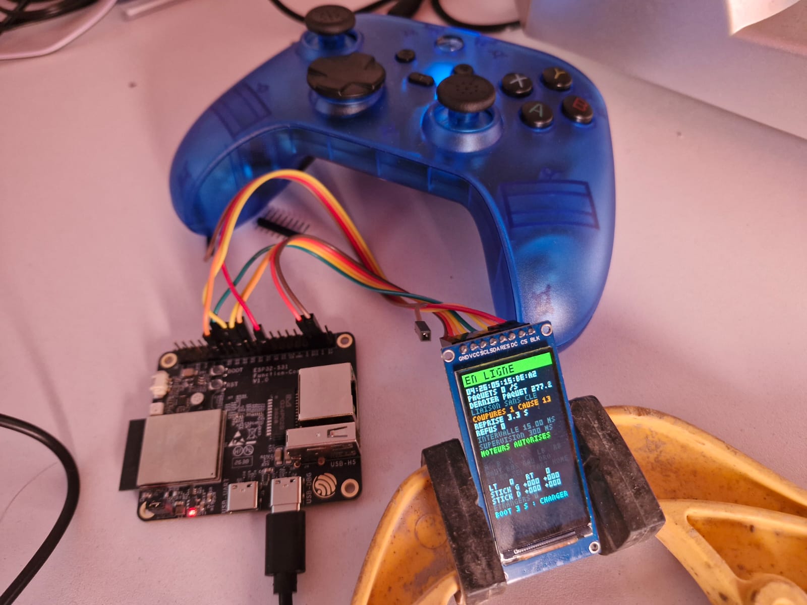
The hardware on the table
The board is an ESP32-S31 Function-CoreBoard-1 from Espressif. A development board is a small board sold by a microcontroller manufacturer: it carries the chip, its power supply, its USB ports, and a connector exposing its pins, so you can write and test a program before the final circuit board exists. This one carries an ESP32-S31-WROOM-3 module: two RISC-V cores at 320 MHz, 16 MB of flash memory, 16 MB of external RAM, Wi-Fi 6, Bluetooth 5.4, and even an Ethernet port. Its pins are brought out to a 40-pin connector labeled J2 on the board.
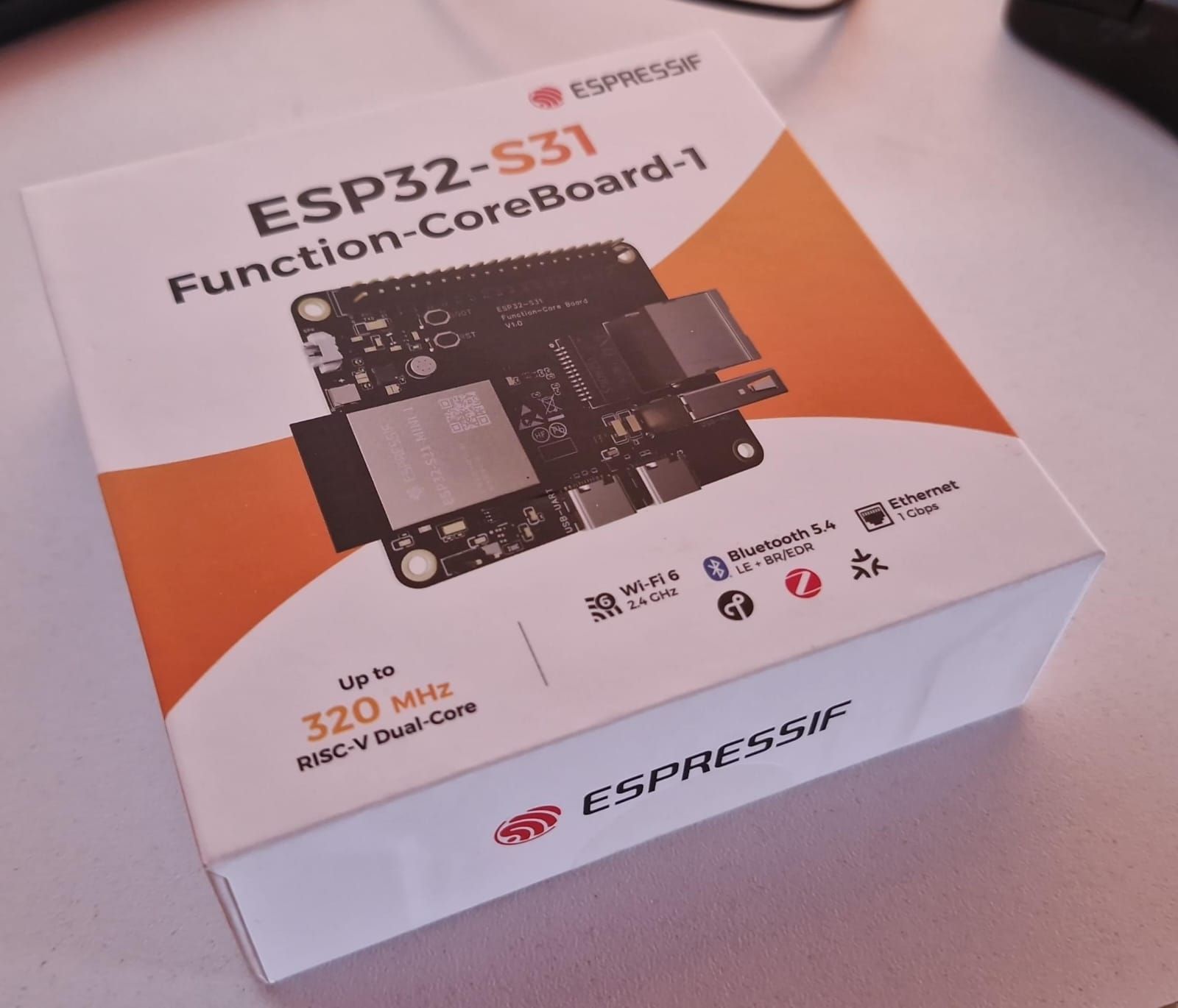
It has two USB-C ports. The one marked USB-DBG is the chip’s native USB port: it is used to flash the program and read the console without pressing any buttons. That is the one we connect. The board also has two buttons: RST, which restarts the chip, and BOOT, connected to pin IO61, which we will use later.
The ESP32-S31 is a recent chip. ESP-IDF, Espressif’s official development framework (the libraries, compiler, and tools), still lists it among the “preview” chips in version 6.1: every command must acknowledge this with the --preview option, otherwise it refuses to compile for the chip.
To see what the board is doing without keeping a computer connected, we add a 1.9-inch ST7789 display, 170 × 320 pixels, driven by an SPI bus (a clocked serial link over which the board sends commands and pixels on two lines). The robot will have the same one.
That leaves the controller. It is a BSP-G6, sold for playing games on a phone. Its manual has been lost, so everything that follows was learned by interrogating it.
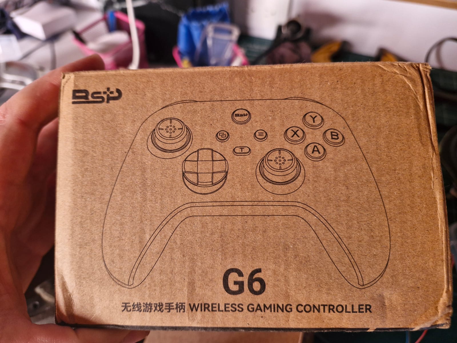
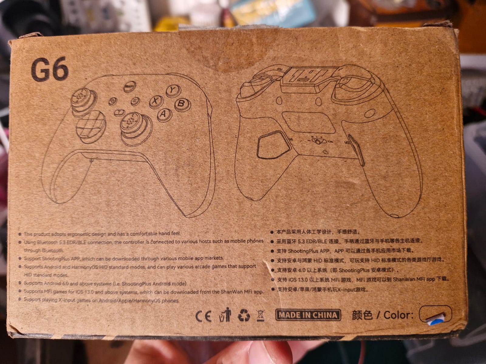
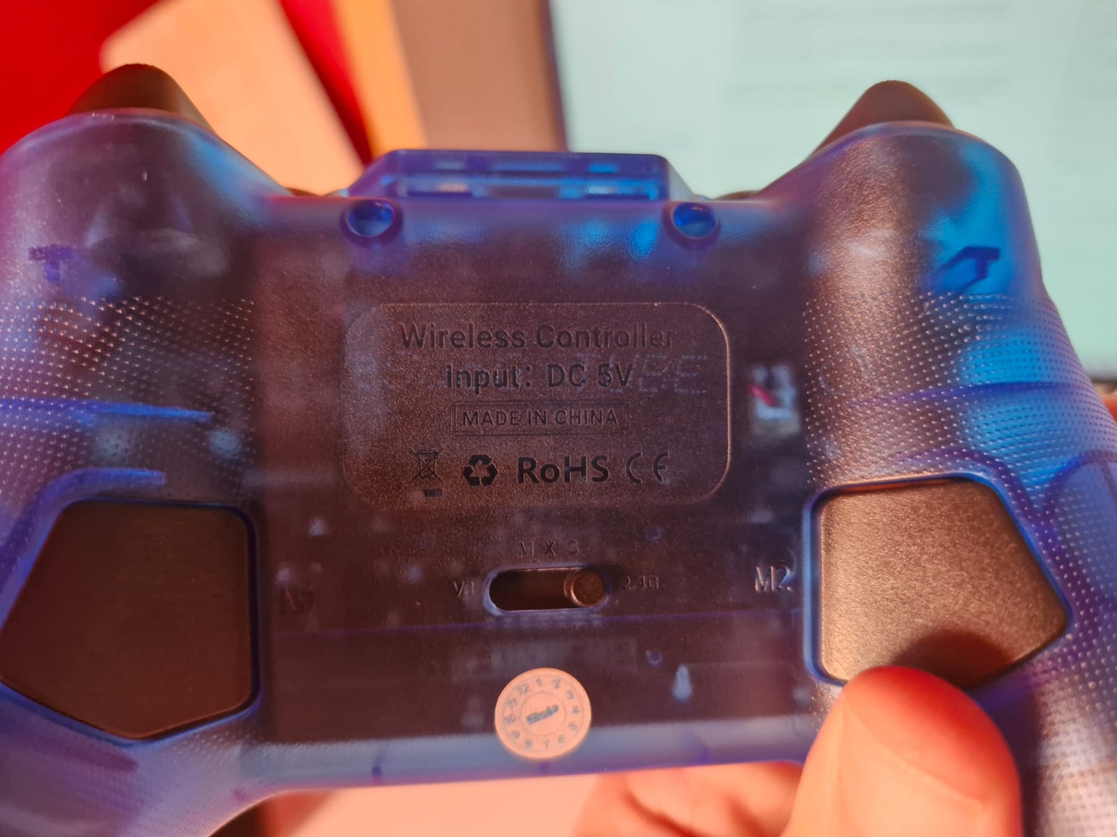
On the back of the controller, below the label, a five-position switch selects its mode: V3, M, X, S, and 2.4G. On either side, two paddles marked M1 and M2 sit under your fingers. By the end of the third trial, we will know what they do.
The program is written in C++ using ESP-IDF 6.1. Bluetooth is handled by Bluedroid, the Bluetooth stack supplied by ESP-IDF (the stack is the set of software layers between the radio and the program).
Trial 01: a display to see what the board is doing
Before listening to the controller, we needed a way to display what we heard. Eight female-to-female jumper wires connect the display to connector J2, with the board unplugged from USB while wiring:
| Display | J2 pin (silkscreen) | Chip pin | Purpose |
|---|---|---|---|
| GND | 34 (G) | — | ground |
| VCC | 36 (3V3) | — | 3.3 V supply |
| SCL | 20 (42) | IO42 | SPI bus clock |
| SDA | 17 (43) | IO43 | SPI bus data |
| RES | 14 (48) | IO48 | display reset |
| DC | 16 (46) | IO46 | command or data |
| CS | 11 (49) | IO49 | display chip select |
| BLK | 23 (37) | IO37 | backlight |
There are two traps in this table. VCC goes to 3.3 V, not 5 V: the ESP32’s signals are at 3.3 V, and a display powered at the same level never receives an input voltage higher than its own supply. And SCL and SDA are not an I²C bus, despite the names module vendors give them: they are the SPI bus clock and data lines. Use the silkscreen printed next to each J2 pin rather than counting pins: the markings on the board in your hand are what matter.
In the program, this wiring comes down to a few constants:
constexpr gpio_num_t BROCHE_SCLK = GPIO_NUM_42;  // horloge SPI   J2 broche 20
constexpr gpio_num_t BROCHE_MOSI = GPIO_NUM_43;  // données SPI   J2 broche 17
constexpr ecran::Broches BROCHES_ECRAN = {
    .cs = GPIO_NUM_49,   // sélection       J2 broche 11
    .dc = GPIO_NUM_46,   // cmd. / donnée   J2 broche 16
    .rst = GPIO_NUM_48,  // remise à zéro   J2 broche 14
    .blk = GPIO_NUM_37,  // rétroéclairage  J2 broche 23
};
constexpr spi_host_device_t BUS_SPI = SPI3_HOST;
constexpr unsigned FREQUENCE_SPI_HZ = 20 * 1000 * 1000;
The ST7789 chip can drive panels of several sizes, each with its own settings. To find them, the first program drew a test pattern: a one-pixel white frame on all four edges, a yellow square in one corner, and four red, green, blue, and white bands. Each possible fault leaves a different trace: a frame cut off on the left points to a horizontal offset, negative colours mean inversion is needed, and swapped red and blue reveal the colour order. The test pattern was correct on the first try with these settings:
// La dalle de 1,9 pouce, 170 × 320 : la puce a 240 colonnes de mémoire, la dalle
// n'en montre que les 170 du milieu, d'où le décalage de (240 − 170) / 2 = 35.
constexpr Dalle DALLE_1_9_POUCE = {170, 320, 35, 0, true, LCD_RGB_ELEMENT_ORDER_RGB};
The true requests colour inversion: IPS panels like this one display a negative image without it.
One fault did appear later, though, and it is worth telling. The correct test pattern suddenly turned into its exact negative after the board was moved: white background, red turned cyan, green turned magenta. Nothing was damaged. At startup, the program sends the display a sequence of commands, including CASET (code 0x2A, binary 00101010), which selects the columns to write to. The most likely explanation is that a wire made poor contact at the wrong moment, and two of those bits were read as zero. That leaves 00100000, or 0x20, which is the INVOFF command: “stop inverting colours.” A poor contact does not necessarily garble a command: it can create another perfectly valid one. The cure: seat the wires firmly, then press RST. The program resends the entire configuration at every startup.
The display runs at 20 MHz over loose wires about ten centimetres long, with no transfer errors. We can move on to the controller.
The complete program for this trial, with its test pattern and its four settings, can be downloaded at the end of the article, under the complete programs.
Trial 02: the controller thinks it is a touchscreen
ESP-IDF provides a ready-made example for reading a Bluetooth input device: esp_hid_host, in the examples/bluetooth directory. It searches for nearby HID devices for a few seconds (Human Interface Device, the standardised family of keyboards, mice, and controllers), connects, then prints each received report to the console: the small packet of bytes the device sends when a button changes.
The example did not find the controller as supplied. Three corrections were needed:
- The controller was detected, then discarded. The example only accepts a device if the HID service appears in its complete list of advertised services. The BSP-G6 puts it in the incomplete list, which the example did not read.
- A connection was never attempted. When Classic Bluetooth is enabled, the example only connects to a device named “HID Mouse Example,” its own demonstration mouse. It now connects to the last HID device found.
- The search sometimes stopped without saying anything. Its two waits now have time limits and announce their completion in the console.
With the switch on V3 and HOME held for three seconds (the red LED flashes quickly: this is pairing mode), the controller connected. The console revealed its identity: name “BSP-G6,” manufacturer “ShanWan BM-835,” vendor and product IDs 1949:0402.
Then the reports arrived, and they were strange. A single 17-byte report: four groups of four bytes, followed by one last byte counting the fingers. The controller described itself as a four-finger touchscreen. In each group, the first byte holds the finger number and its state, and the next three hold its position. For example, the group 13 3d 44 ad reads as follows:
13: finger no. 1 (the left hexadecimal digit), touching (the3on the right; a2would mean lifted);3d 44 ad: two interleaved 12-bit numbers, X =0x43D= 1085 and Y =0xAD4= 2772.
This is the “mapping mode” of phone controllers, intended for games that only understand a touchscreen: a stick slides a virtual finger, and a button places one at a fixed point on the screen. Those points are configured in the manufacturer’s app. For a robot, this is unusable: the position of a “button” would depend on a setting made on a phone.
The program for this trial, the ESP-IDF example with its three corrections, can be downloaded at the end of the article, under the complete programs.
Five positions, three identities
The five-position switch therefore changes the controller’s very nature. Three positions were investigated using the board, a phone, and a Windows PC:
| Position | Radio | Presents itself as | Radio address |
|---|---|---|---|
| V3 | Bluetooth Low Energy (BLE) | a four-finger touchscreen, “BSP-G6” | 01:26:05:15:BE:A2 |
| X | Classic Bluetooth | an Xbox One S controller, “Xbox Wireless Controller” | 83:26:05:15:BE:A2 |
| 2.4G | Bluetooth Low Energy (BLE) | a game controller, “BM769 24G”: six axes, sixteen buttons, and a D-pad | 04:26:05:15:BE:A2 |
The three addresses differ only in their first byte: one radio, three identities. In X, the controller imitates an Xbox controller over Classic Bluetooth, a known format; but under Windows it only worked with its cable plugged in. The 2.4G position held a surprise: you would expect a proprietary 2.4 GHz link with a supplied USB receiver; it is actually BLE (Bluetooth Low Energy, which also transmits at 2.4 GHz). And its description is that of a real game controller. Windows registered it as an “HID game controller”… and nothing moved in its test panel, whatever buttons were pressed.
It was still the most promising position. We needed to see what it actually sent, without assuming anything about its format.
Trial 03: display everything, bit by bit
The third program decodes nothing. It displays each received byte on one row of the screen, with its eight bits in eight cells: a 1 bit in light blue, a 0 bit in dark blue-grey. A bit that has just changed keeps another colour for half a second: pale yellow if it changes to 1, khaki if it drops back to 0. A button is therefore identified by the cell that lights up pale yellow when pressed; a stick makes several cells in one or two bytes flash at once. In the video, pale yellow is visible around the fourth second; khaki lasts only an instant, around the ninth.
Before we got there, three console messages stopped the controller, each in turn.
The connection dropped immediately, with code 0x3d: “encryption integrity check failed.” The board had started link encryption using a key saved from a previous pairing that the controller no longer recognised; trial 04 will explain why. The program now erases all keys at startup.
Subsequent attempts were rejected by the radio, with Cmd Disallowed. As soon as a BLE 5.0 feature is used, the stack switches to BLE 5.0 “extended” connections, which the radio rejects after a BLE 4.2-style scan. A controller does not need BLE 5.0: it is disabled in the project settings.
Then the console started scrolling, two hundred times a second: drop notif, handle 0x002e not registered. The stack was receiving packets from the controller and discarding them because nobody had subscribed to their source.
To understand this message, we need to know how a BLE device organises its data. It presents it in a catalog, GATT (a BLE device’s data catalog), made up of services (families of data), themselves made up of characteristics (a data item that can be read, written, or received automatically). Each catalog entry has an address number, its handle. A characteristic can send its value on its own whenever it changes: this is a notification, and you must subscribe to receive it. Here is the controller’s catalog in the 2.4G position, as read by the board:
| Handles | Service | Contents |
|---|---|---|
0x01 to 0x07 | 0x1800, Generic Access | the name “BSP-G6-HID,” appearance |
0x08 to 0x0B | 0x1801, Generic Attribute | — |
0x0C to 0x12 | 0x180A, Device Information | manufacturer “ShanWan BM-835” |
0x13 to 0x23 | 0x1812, HID | a description of a 10-byte controller. No packets travel through it |
0x24 to 0x29 | 0xFFFF, vendor-specific | silent |
0x2A to 0x2F | 91680001-…, vendor-specific | characteristic 91680003, handle 0x2E: everything goes through it |
0x30 to 0x35 | 95990001-…, vendor-specific | silent |
That explains the Windows mystery. The HID service, the only one listened to by Windows and ESP-IDF’s HID reader, really does describe a controller, but transmits nothing. The buttons travel over a vendor service identified by a UUID (a 128-bit identifier) that nothing associates with a game controller: 91680001-1111-6666-8888-0123456789AB. Subscribing to the right handle (the address number of a data item inside the controller) was enough to bring the grid to life.
Subscribing: what the board had not done
“Nobody had subscribed to their source”: a short sentence hiding the most useful mechanism in all of BLE. It deserves a closer look.
Two ways to obtain a value. A central (the device that chooses whom to connect to, here the board) can obtain a characteristic’s value in two ways. It can read it: it sends a request over the radio, and the peripheral replies. That is a phone call to ask for a match score. Or it can subscribe: the peripheral sends the value on its own whenever it changes, in a notification. That is the message you receive for each goal without asking. For a controller, the difference is considerable. Reading its buttons a hundred times a second would mean a hundred requests and a hundred replies, and a button press would arrive half a polling period late on average. With a subscription, the controller only speaks when a button changes, and the packet leaves at the next radio rendezvous.
A subscription needs two registers. “Subscription” is a good word: as with a newspaper, the publisher must know to send it, and someone at home must collect the mail. A BLE notification likewise passes through two registers, one in each device.

The board’s register (① in the figure). Several programs on the board can share a radio link: in trial 03, ESP-IDF’s HID reader and our program were listening to the same controller. All notifications on the link therefore reach the board’s Bluetooth stack first, which must decide which program should receive each one. It keeps a register for this purpose: this handle, this program. A program registers using esp_ble_gattc_register_for_notify, supplying the handle it expects. A notification whose handle appears in no entry is expected by nobody: the stack discards it and prints the fact to the console. That is exactly the message from trial 03. The HID reader had registered for its service’s handles, 0x1B and 0x17; nobody had done so for 0x2E, and two hundred packets a second went into the trash.
The controller’s register (② in the figure). Each characteristic capable of sending notifications carries a small two-byte data item, its subscription descriptor (the Client Characteristic Configuration Descriptor, UUID 0x2902). The central writes what it wants to receive into it:
| Written value | What the peripheral does |
|---|---|
00 00 | stays silent: this is the initial value |
01 00 | notifies: sends the value whenever it changes, without waiting for a reply |
02 00 | indicates: sends the value, then waits for the central to acknowledge receipt before sending the next one |
The two bytes are read least significant first: 01 00 is the number 1. An indication provides stronger delivery assurance because every transmission is acknowledged, but it costs a radio round trip for each value. For a controller, notification is a better fit: if a packet is lost, the next one arrives at the following radio rendezvous, and it carries the controller’s complete state, not just what changed.
The two registers serve different purposes. The controller’s register decides whether it sends. The board’s register decides whether incoming data is delivered to the right program. Without the second, the board discards what it receives. Without the first, a standards-compliant controller stays silent. The BSP-G6, however, was already sending on its channel without anybody having written to its descriptor: in trial 03, only the board’s register was missing.
Two examples beyond our controller.
- A sports heart-rate strap advertises a standard service,
0x180D, whose0x2A37characteristic carries the heart rate. It only sends it once the phone has written01 00to its subscription descriptor. An app that forgets this sees a connected but silent strap: the reverse of our problem. - A device’s battery level (service
0x180F, characteristic0x2A19) lends itself to either approach. A phone can read it when displaying the devices screen, or subscribe to be notified whenever it drops.
In the program, subscription happens in this order. Once the catalog has been read, the board finds the controller’s channel by its UUID, saves its handle, and registers with its stack (①):
esp_gattc_char_elem_t canal = {};
uint16_t nombre = 1;
esp_bt_uuid_t uuid = {};
uuid.len = ESP_UUID_LEN_128;
std::memcpy(uuid.uuid.uuid128, UUID_DU_CANAL, 16);
if (esp_ble_gattc_get_char_by_uuid(interface_, session_, debut_du_service_, fin_du_service_, uuid, &canal,
                                   &nombre) != ESP_GATT_OK ||
    nombre == 0) {
    refuser(-6, "canal du fabricant introuvable dans son service");
    break;
}
handle_du_canal = canal.char_handle;
esp_ble_gattc_register_for_notify(interface_, adresse_liee_, canal.char_handle);
The stack confirms registration with an event (ESP_GATTC_REG_FOR_NOTIFY_EVT). The board then writes 01 00 to the controller’s subscription descriptor (②), after finding it among the characteristic’s descriptors:
void Liaison::ecrire_l_abonnement(uint16_t handle_de_caracteristique)
{
    esp_gattc_descr_elem_t descripteur = {};
    uint16_t nombre = 1;
    esp_bt_uuid_t uuid = {};
    uuid.len = ESP_UUID_LEN_16;
    uuid.uuid.uuid16 = UUID_DU_DESCRIPTEUR_D_ABONNEMENT;
    if (esp_ble_gattc_get_descr_by_char_handle(interface_, session_, handle_de_caracteristique, uuid, &descripteur,
                                               &nombre) == ESP_GATT_OK &&
        nombre > 0) {
        uint8_t valeur[2] = {0x01, 0x00};
        esp_ble_gattc_write_char_descr(interface_, session_, descripteur.handle, sizeof valeur, valeur,
                                       ESP_GATT_WRITE_TYPE_RSP, ESP_GATT_AUTH_REQ_NONE);
    }
}
ESP_GATT_WRITE_TYPE_RSP requests a write with response: the controller confirms that it has recorded the subscription. From then on, each notification from handle 0x2E reaches the program’s recevoir_un_paquet function, detailed later in trial 04.
A subscription does not survive the link. At every disconnection, the board’s stack clears the entries in its register for that link. And the standard requires the peripheral to reset its descriptor to 00 00 on each new connection, except for a central it has bonded with, whose settings it retains. Our board, as we will see, does without bonding: both registers are therefore empty at every reconnection. That is why the program repeats both registrations at every connection, rather than just once at startup. A program that only subscribes at startup works until the first disconnection, then stays connected and silent.
Only subscribe to what you read. Subscribing to every characteristic on a device “to see what happens” is tempting during an investigation, but every subscription generates radio traffic. The final program registers only for handle 0x2E. Notifications from other handles are discarded by the stack before reaching it; if a packet from another handle did reach it anyway, it would be counted on screen as “foreign” and ignored.
To perform the same investigation on another controller, you therefore need to register for each characteristic capable of sending notifications. A few lines in the function that receives ESP-IDF GATT client events are then enough to print each notification to the console, with its handle and bytes:
case ESP_GATTC_NOTIFY_EVT:
    ESP_LOGI(TAG, "handle 0x%04X, %d octets", p->notify.handle, p->notify.value_len);
    ESP_LOG_BUFFER_HEX(TAG, p->notify.value, p->notify.value_len);
    break;
Mapping the buttons, one by one
Each packet from channel 0x2E is 20 bytes long and always starts with 20 0F. To assign each cell to its button, a first pass followed an agreed order. The second was smarter: each button was pressed a different number of times, from one to four, in two groups. The number of flashes in a cell then identifies its button regardless of the order in which they were pressed, so an ordering mistake can no longer corrupt the mapping. Here is the result:
| Byte | Contents | Values |
|---|---|---|
| 0 and 1 | header | always 0x20, 0x0F |
| 3 and 4 | left stick, X then Y | 0x80 at centre; X = 0xFF pushed right; Y = 0x00 pushed up |
| 5 and 6 | right stick, X then Y | same |
| 7 | A, B, X, Y, and D-pad | A 0x10 · B 0x20 · X 0x40 · Y 0x80 · up 0x01 · down 0x02 · left 0x04 · right 0x08 |
| 8 | digital shoulder buttons, stick clicks, centre buttons | LB 0x01 · RB 0x02 · left click 0x04 · right click 0x08 · “double screen” 0x10 · “list” 0x20 · HOME 0x40 |
| 10 | left analogue trigger | from 0x00 at rest to 0xFF fully pressed |
| 11 | right analogue trigger | same |
| 13 to 16 | a second copy of the stick positions | meaning not established |
The other bytes did not change, or not in a way we could relate to an action. Several buttons pressed together combine bit by bit: 0x03 in byte 8 means both digital shoulder buttons. The T button in the centre sends nothing: it is the “turbo” button, which makes another button repeat while held down.
In the final program, this mapping becomes a table, and decoding becomes a loop:
struct Bouton {
    const char *mot;
    uint8_t octet;
    uint8_t masque;
    int rang;  // ligne de l'écran (à partir de Y_BOUTONS)
    int x;
};
constexpr Bouton BOUTONS[] = {
    {"A", 7, 0x10, 0, 2},       {"B", 7, 0x20, 0, 26},      {"X", 7, 0x40, 0, 50},   {"Y", 7, 0x80, 0, 74},
    {"LB", 8, 0x01, 0, 106},    {"RB", 8, 0x02, 0, 138},    {"HAUT", 7, 0x01, 1, 2}, {"BAS", 7, 0x02, 1, 42},
    {"GAU", 7, 0x04, 1, 74},    {"DRO", 7, 0x08, 1, 106},   {"L3", 8, 0x04, 2, 2},   {"R3", 8, 0x08, 2, 26},
    {"SEL", 8, 0x10, 2, 50},    {"START", 8, 0x20, 2, 82},  {"HOME", 8, 0x40, 2, 130},
};

Commandes decoder(const uint8_t p[TAILLE_DU_PAQUET])
{
    Commandes c = {};
    for (int i = 0; i < NOMBRE_DE_BOUTONS; ++i) {
        if (p[BOUTONS[i].octet] & BOUTONS[i].masque) {
            c.boutons |= 1u << i;
        }
    }
    // 0x80 au milieu ; X = 0xFF à droite ; Y = 0x00 en haut, d'où l'inversion.
    c.stick_g_x = p[3] - 128;
    c.stick_g_y = 128 - p[4];
    c.stick_d_x = p[5] - 128;
    c.stick_d_y = 128 - p[6];
    c.gachette_g = p[10];
    c.gachette_d = p[11];
    return c;
}
Each entry in BOUTONS says where to read a button: which byte, and with which mask (the number that keeps only the desired bit). The operation p[octet] & masque is zero if the bit is 0, and nonzero if it is 1. The last two numbers position the label on screen. Adding a button means adding a table entry, without changing the loop. The sticks are recentred around zero, from −128 to +127, and the vertical axis is reversed so that “up” is positive, as on a graph.
The two rear paddles
That left M1 and M2. Pressing them lit up no cells. They are macro keys, empty from the factory: the controller can record a sequence of buttons and replay it with a single press. The procedure comes from the manual for a G6 controller in the same family, which covers the BSP-G6:
- Hold the “double screen” button (two overlapping rectangles in the centre) and press M1; after one second, the LED flashes quickly.
- Press the desired buttons in order, up to twelve.
- Press M1 again: the LED becomes steady again.
With B, Y, X, A recorded, paddle M1 makes byte 7 step through 0x20, 0x80, 0x40, then 0x10, at roughly one button every 50 ms. The board receives the replayed buttons, with nothing identifying the paddle. For the robot, the consequence is simple: a paddle is never an extra command, only a shortcut to existing buttons. The analogue triggers are also replayed at full travel, without the finger’s gradual movement.
The fault visible in the video
Look again at the video’s banner: it says RECHERCHE (“searching”) even though packets are arriving and the grid is moving. The radio was not to blame. On the board, two programs were listening to the same link: ESP-IDF’s HID reader, which had opened it, and ours, subscribed to channel 0x2E. The banner followed the first. The HID reader had closed its session for a reason the console did not reveal; ours remained open, and the link with it.
For a robot, this kind of mismatch is serious: it says “no controller” when one is present, and could say the reverse. The displayed state must be the state of the link itself, and only one program should be listening to it. That will be the first rule of the fourth trial.
The program for this trial, the one that draws the grid, can be downloaded at the end of the article, under the complete programs. It is all you need to map the bytes of another controller.
Trial 04: a link that talks only to its own controller
At a competition, dozens of identical controllers may advertise in the same hall. Two requirements follow: someone else’s controller must never be able to connect to the robot, and our link must not be disrupted without the robot knowing. The fourth program was written for this purpose: it is the final program, which can be downloaded at the end of the article together with those of the first three trials, under the complete programs. It no longer uses ESP-IDF’s HID reader: in the 2.4G position, there was nothing for it to read.
In BLE, the central chooses
A BLE link brings together two roles. The peripheral, here the controller, advertises: it periodically broadcasts an advertisement (a short radio message saying “I am here,” with its address). The central, here the board, listens to those advertisements and chooses whom to connect to. A controller therefore cannot force itself onto a central that does not call it.
All the protection rests on this point. Once the controller is known, the board stores its address and calls only that address. ESP-IDF calls this a direct connection:
void Liaison::ouvrir(const uint8_t adresse[6], esp_ble_addr_type_t type)
{
if (ouverture_en_cours_ || liaison_ouverte_ || interface_ == ESP_GATT_IF_NONE) {
return;
}
// « is_direct » : la radio guette les annonces de CETTE adresse, et d'elle
// seule, jusqu'à 30 s (CONFIG_BT_BLE_ESTAB_LINK_CONN_TOUT). C'est ce qui
// garantit qu'aucune autre manette ne peut être prise.
esp_ble_gatt_creat_conn_params_t parametres = {};
std::memcpy(parametres.remote_bda, adresse, 6);
parametres.remote_addr_type = type;
parametres.own_addr_type = BLE_ADDR_TYPE_PUBLIC;
parametres.is_direct = true;
parametres.is_aux = false; // connexion BLE 4.2 : le 5.0 est coupé (sdkconfig.defaults)
parametres.phy_mask = 0;
if (esp_ble_gattc_enh_open(interface_, ¶metres) == ESP_OK) {
ouverture_en_cours_ = true;
} else {
ESP_LOGE(TAG, "connexion refusée par la pile ; nouvel essai dans 1 s");
programmer(AFaire::Ouvrir, 1000 * 1000);
}
}For thirty seconds, the radio listens only for advertisements from that address. If the controller has not advertised, the attempt fails, and the program immediately starts another, indefinitely. The board therefore never needs to “search” for the controller: it is permanently ready to take it back as soon as it advertises. is_aux = false requests a BLE 4.2-style connection, for the reason discovered in trial 03.
Learn a controller only through a deliberate action
We still need to learn its address, once, without risking saving the neighbor’s. Two conditions must be met. First, a deliberate action: holding the board’s BOOT button for three seconds. Then a controller very close by: the board retains the strongest HID device seen during a three-second scan and accepts it only if its signal reaches −60 dBm. This value is the RSSI (received signal strength, in decibels relative to one milliwatt): −60 dBm corresponds to a few tens of centimetres. A controller at the other end of the hall has no chance of being selected by mistake.
case Quoi::FinDeRecherche:
    recherche_en_cours_ = false;
    if (!appairage_) {
        break;
    }
    if (candidat_ && signal_du_candidat_ >= SEUIL_D_APPAIRAGE_DBM) {
        ESP_LOGI(TAG, "appairage avec " ESP_BD_ADDR_STR " (%d dBm)", ESP_BD_ADDR_HEX(adresse_du_candidat_),
                 signal_du_candidat_);
        ouvrir(adresse_du_candidat_, type_du_candidat_);
    } else {
        rechercher();  // personne d'assez proche : on recommence
    }
    break;
The BOOT button has a peculiarity: the chip reads its level at startup to choose between running the program and waiting for a firmware download. Holding it during a restart would therefore boot the board into download mode. The program only reads it once it is running, every 10 ms, in a separate task:
// Le bouton BOOT : 3 s tenu, une seule fois par appui.
if (gpio_get_level(BROCHE_BOOT) == 0) {
    if (boot_presse_depuis == 0) {
        boot_presse_depuis = maintenant;
    }
    const int64_t tenu = maintenant - boot_presse_depuis;
    boot_tenu_ms = static_cast<int32_t>(tenu / 1000);
    if (tenu >= DUREE_POUR_APPAIRER_US && !boot_signale) {
        boot_signale = true;
        poster(evenement(Quoi::Boot));
    }
} else {
    boot_presse_depuis = 0;
    boot_signale = false;
    boot_tenu_ms = 0;
}
The saved address is stored in the ESP32’s settings memory (a flash memory area called NVS that survives power loss). Restarting the board does not erase it; only another three-second press of BOOT allows the controller to be changed.
Silence is not a fault
The first version monitored the link in the most obvious way: if no data packet arrives for 200 ms, stop the motors. Left on the table, the controller immediately went “silent,” with the motors stopped. It only sends a data packet when a button or stick changes. A stick held motionless at full travel would also have stopped the motors in the middle of a run.
Is there not a continuous dialogue to maintain the connection? There is, but at a different layer: the radio. Once connected, the central and peripheral meet at fixed intervals, and at each rendezvous they exchange a packet, empty if they have nothing to say. This rhythm is the connection interval. If these exchanges stop for a set time, the supervision timeout, the radio declares the link lost. The heartbeat already exists; we only needed to listen in the right place.
On connection, the controller proposed a 25 ms interval and a 6-second supervision timeout. Six seconds of a robot running blind before discovering the controller is lost: far too long. But the central sets these parameters. The board therefore requests better ones as soon as it connects:
constexpr uint16_t INTERVALLE_MIN = 6; // 7,5 ms
constexpr uint16_t INTERVALLE_MAX = 12; // 15 ms
constexpr uint16_t DELAI_DE_SUPERVISION = 30; // 300 ms
void Liaison::demander_les_parametres()
{
esp_ble_conn_update_params_t parametres = {};
std::memcpy(parametres.bda, adresse_liee_, 6);
parametres.min_int = INTERVALLE_MIN;
parametres.max_int = INTERVALLE_MAX;
parametres.latency = 0; // la manette répond à CHAQUE rendez-vous radio
parametres.timeout = DELAI_DE_SUPERVISION;
if (esp_ble_gap_update_conn_params(¶metres) != ESP_OK) {
ESP_LOGW(TAG, "demande de paramètres de liaison refusée par la pile");
}
}The units are those of the Bluetooth standard: the interval is counted in 1.25 ms steps (6 steps make 7.5 ms, 12 steps make 15 ms), and the supervision timeout in 10 ms steps (30 steps make 300 ms). Latency is the number of rendezvous the peripheral is allowed to skip to save battery power; at zero, it responds to every one.
The standard imposes a condition linking these numbers so the link cannot be declared lost before it has even had time to miss an exchange:
With a 15 ms interval and zero latency, more than 30 ms is required: our 300 ms allows about twenty missed rendezvous before reaching a conclusion. Why not less? The standard forbids going below 100 ms, and too short a timeout would let the slightest brief interference drop the link, which then takes close to a second to restore. Too long, and the robot would run blind. 300 ms is a starting point to be adjusted through tests under competition conditions. The controller accepted these parameters: 15 ms and 300 ms. On the robot, the motors will be stopped the instant the radio declares the link lost.
The key the controller forgets
The first program of the fourth trial encrypted the link. During pairing (the first meeting of two devices, when they create a shared key that they keep), the board and controller agreed on a key that the board then reused at every reconnection. As long as the controller stayed on, all was well. Switched off and back on, it rejected its own key: the link dropped with code 0x3d, “encryption integrity check failed,” on every attempt. This was not a missing key, which would give another code (0x06); everything behaves as though the controller creates a new key at each startup.
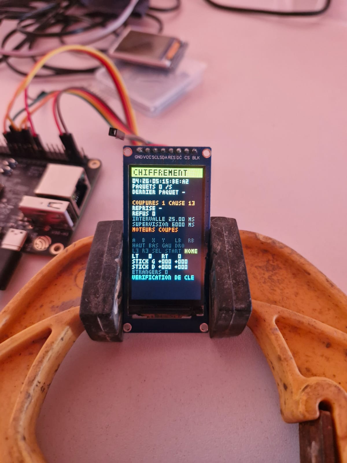
The next workaround was to automatically pair the saved controller again, and only that one, whenever its key stopped working. The controller did not respond. It only accepts pairing in its own pairing mode, with HOME held for three seconds, and the link died after six seconds without a response.
One question remained: does the controller really require encryption? It does not. On channel 0x2E, it sends its packets in plaintext as soon as it connects, without waiting for any key. The program therefore does without a key, through a single setting:
constexpr bool CHIFFRER = false;We must be honest about what remains protected. The board calls only the saved address, and only the BOOT button can change it: no other controller can be selected by mistake or force a connection. What is no longer protected is impersonation by a device built specifically to pose as our controller by copying its address. In competition, the everyday risk is the neighbor’s controller, and that is ruled out; a deliberate attack is a different matter, but it needed to be named. The encrypted path remains in the program: setting CHIFFRER to true restores it for another controller that retains its key.
Without a key, connection comes down to three actions: check that the connected device really is the saved controller, request the connection parameters, then read the catalog to find the channel:
if (!CHIFFRER) {
    // Sans clé : on fixe les paramètres de liaison, puis on lit le
    // canal. Hors appairage, l'adresse est forcément la retenue (la
    // carte n'en appelle pas d'autre) ; on le vérifie quand même.
    if (!appairage_ && std::memcmp(adresse_liee_, manette_.adresse, 6) != 0) {
        refuser(-3, "appareil autre que la manette retenue");
        break;
    }
    demander_les_parametres();
    lire_le_plan();
    break;
}
One detail matters: at startup, in keyless mode, the program erases any keys the Bluetooth stack might have saved. Otherwise, the stack would use them on its own if the controller ever requested encryption, and the old key would fail with the same 0x3d.
The controller’s catalog, meanwhile, is kept in settings memory through CONFIG_BT_GATTC_CACHE_NVS_FLASH: on reconnection, the board does not request it from the controller again, shortening recovery. Once the channel has been found, the board subscribes at both ends, as trial 03 showed: first in its own stack, then in the controller’s subscription descriptor. Both subscriptions are cleared at every disconnection, so they are repeated at every connection, and their confirmation is what switches the screen to EN LIGNE (“online”).
Only one task decides
The program is divided into four tasks (pieces of program that run as if they were alone, which the small FreeRTOS operating system switches between according to their priority):
- The Bluetooth stack calls two program functions at each radio event. A controller packet is handled there and then, in a few microseconds; everything else is posted to a message queue (a mailbox between two tasks).
- The “liaison” (“link”) task drains that queue. It alone decides what the link does: connect, disconnect, pair, reject. Two pieces of program deciding independently would eventually contradict each other, as in trial 03.
- The “guet” (“watch”) task checks the BOOT button every 10 ms.
- The “affichage” (“display”) task redraws only the screen lines that have changed, ten times a second.
The program’s most frequently traveled path is that of a controller packet. It only checks, copies, and counts:
void recevoir_un_paquet(uint16_t handle, const uint8_t *octets, uint16_t longueur)
{
    // Un paquet qui n'a pas la forme attendue (20 octets, commençant par 0x20
    // 0x0F, relevé de l'essai 03) n'est pas pris : il ne nourrit pas le guet.
    if (handle != handle_du_canal || longueur != TAILLE_DU_PAQUET || octets[0] != 0x20 || octets[1] != 0x0F) {
        paquets_etrangers++;
        return;
    }
    instant_du_dernier_paquet = esp_timer_get_time();
    portENTER_CRITICAL(&verrou_du_paquet);
    std::memcpy(dernier_paquet, octets, TAILLE_DU_PAQUET);
    portEXIT_CRITICAL(&verrou_du_paquet);
    paquets_recus++;
}
The program keeps the latest packet, not a queue of packets: the robot needs the controller’s present state, not its history. Copying happens inside a critical section (a section so short that other tasks are prevented from slipping in while it runs), so the display never reads a half-copied packet. The counters are atomic variables (std::atomic, variables two tasks can read and write at the same time without ever reading a half-written value).
Startup puts everything in place in a precise order:
file_de_la_liaison = xQueueCreate(48, sizeof(Evenement));
if (file_de_la_liaison == nullptr) {
    ESP_LOGE(TAG, "pas de mémoire pour la file de la liaison");
    return;
}
xTaskCreate(liaison, "liaison", 6 * 1024, nullptr, 4, nullptr);
xTaskCreate(guetter, "guet", 3 * 1024, nullptr, 6, nullptr);
xTaskCreate(afficher, "affichage", 6 * 1024, nullptr, 3, nullptr);

// 5. Le Bluetooth, en dernier : ses événements trouvent la file prête.
ESP_ERROR_CHECK(demarrer_le_bluetooth());
Bluetooth starts last: its first events therefore find the queue and the task that drains it already ready. The watch task has the highest priority (6), because it must run every 10 ms whatever happens; the display has the lowest (3), because a late image costs nothing.
One final coding detail cost a compilation. The ESP-IDF macro that prepares the radio configuration, BT_CONTROLLER_INIT_CONFIG_DEFAULT, does not give every field of the structure a value for the ESP32-S31. C silently sets omitted fields to zero; C++ warns about them, and ESP-IDF turns every warning into an error. We silence that particular warning on this line only:
#pragma GCC diagnostic push
#pragma GCC diagnostic ignored "-Wmissing-field-initializers"
    esp_bt_controller_config_t config_radio = BT_CONTROLLER_INIT_CONFIG_DEFAULT();
#pragma GCC diagnostic pop
Finally, the project settings are in sdkconfig.defaults. Here is their core: BLE-only Bluetooth, without Classic Bluetooth, which would merely occupy the radio, and without BLE 5.0:
CONFIG_BT_ENABLED=y
CONFIG_BT_BLUEDROID_ENABLED=y
CONFIG_BTDM_CTRL_MODE_BLE_ONLY=y
# CONFIG_BT_CLASSIC_ENABLED is not set
CONFIG_BT_BLE_ENABLED=y
CONFIG_BT_GATTC_ENABLE=y
CONFIG_BT_BLE_SMP_ENABLE=y
CONFIG_BT_BLE_42_FEATURES_SUPPORTED=y
# CONFIG_BT_BLE_50_FEATURES_SUPPORTED is not set
CONFIG_BT_GATTC_CACHE_NVS_FLASH=y
What the display shows, and what it measured
The fourth trial’s display no longer shows bits, but the link state. The banner identifies the stage:
| Banner | What is happening |
|---|---|
| SANS MANETTE (grey, “no controller”) | no controller saved: learn one by holding BOOT for 3 s |
| APPAIRAGE (cyan, “pairing”) | the board is searching for a controller in pairing mode very close to it |
| ATTENTE (orange, “waiting”) | the board is waiting for the saved controller to advertise |
| LECTURE (yellow, “reading”) | connected: reading the catalog and subscribing to the channel |
| EN LIGNE (green, “online”) | the link is established and commands are arriving |
Below the banner comes the saved controller’s address, then the measurements: packet rate, time since the last data packet, number of disconnections with their cause codes, recovery time after the last disconnection, rejections, and the two connection parameters. The MOTEURS AUTORISES line (green, “motors enabled”) or MOTEURS COUPES line (red, “motors stopped”) says what the robot would do. Farther down, each pressed button lights up yellow, and the triggers and sticks are shown as numbers.
The opening photo sums up the whole chapter on silence: DERNIER PAQUET 277.8 S (“last packet 277.8 s”), no data packet for more than four and a half minutes, yet still EN LIGNE, MOTEURS AUTORISES. Nobody was touching the controller, and the radio kept beating every 15 ms.
Measurements taken on November 20, 2026:
- Board restart, with the controller still on: the board picks it up automatically, without any action, and is online less than a second and a half after startup.
- Controller switched off and back on (hold HOME to switch it off, press briefly to switch it on): the board picks it up as soon as it advertises, about twenty milliseconds after the radio link is established, with the catalog read back from settings memory.
- Controller left idle: it disconnected on its own 5 min 11 s after coming online, even with the link open. This is its automatic sleep mode. The board detected it immediately (disconnection, reason
0x13: the remote device terminated the link), and a press of HOME brings it back online.
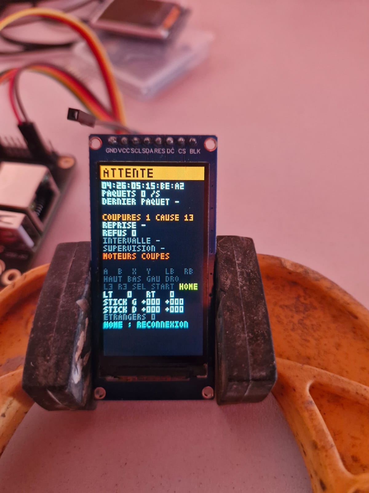
On the robot, this sleep mode will have a practical consequence: a controller left for five minutes during a break must be woken with HOME before taking control again. There is no danger, since the motors stop the instant it disconnects.
Reproducing the build
What you need
- An Espressif ESP32-S31 Function-CoreBoard-1 board and a USB-C cable.
- A 1.9-inch ST7789 display, 170 × 320 pixels, on an eight-pin module (GND, VCC, SCL, SDA, RES, DC, CS, BLK).
- Eight female-to-female jumper wires about ten centimetres long.
- A BSP-G6 controller (ShanWan BM-835). Another controller will need its own investigation using the method from trial 03: its channel and button positions are very likely to differ.
- ESP-IDF 6.1, installed according to Espressif’s documentation (on Windows, through its installer, which sets up a fully configured ESP-IDF terminal).
- The complete project, available to download at the end of the article.
Wiring
Follow the table in trial 01 with the board unplugged. The one wire to double-check is VCC: to 3V3 (J2 pin 36), never to 5V.
Building and flashing
Extract the project into a directory whose path contains no spaces or accented characters, for example C:\esp\manette-ble-esp32-s31 on Windows. Some ESP-IDF 6.1 tools stumble over spaces, accented characters, and long dashes in paths, and their error messages do not explain this clearly. Connect the board through its USB-DBG port, open the ESP-IDF terminal, change to the project directory, then run:
idf.py --preview set-target esp32s31
idf.py --preview build
idf.py --preview -p COM3 flash monitor
The first command selects the chip, the second builds the program (several minutes the first time, a few seconds afterward), and the third flashes it and opens the console. Replace COM3 with your board’s port: Windows lists it as a “USB Serial Device” in Device Manager, Linux as /dev/ttyACM0. No buttons need to be pressed: flashing automatically puts the chip into download mode and then restarts it. Exit the console with Ctrl+].
Learning the controller
- If the controller has already been connected to a phone or PC, make that device forget it in its Bluetooth settings: a controller connected elsewhere stops advertising.
- The screen says SANS MANETTE. Hold BOOT for three seconds: the screen counts the seconds, then switches to APPAIRAGE.
- Set the controller’s switch to 2.4G, hold HOME for three seconds (the LED flashes quickly), and place it beside the board. The screen shows the detected device’s name and signal strength: green if it is close enough, orange if it is too far away.
- Wait for EN LIGNE, then press each button: its name lights up yellow.
- Check recovery: press RST on the board, and it should come back online by itself; switch the controller off (hold HOME), turn it back on with a short press, and the board should pick it up without any further action.
When it does not work
| What you see | What it means | What you can do |
|---|---|---|
| The display lights up but stays uniform, with no text | the display is not receiving its commands | check SCL, SDA, DC, CS, and RES one by one; then lower FREQUENCE_SPI_HZ to 10 MHz |
| The whole screen turns negative after a wire is moved | a poor contact changed a command in transit | seat the wires firmly, then press RST |
| APPAIRAGE never ends, name shown in orange | the controller is too far away (signal below −60 dBm) | move it closer to the board |
| APPAIRAGE never ends, no name displayed | the controller is not in pairing mode, or is connected elsewhere | hold HOME for 3 s; make the phone or PC forget it |
| REFUS MOTIF 6 | the vendor channel cannot be found | the controller is not in the 2.4G position |
| REFUS MOTIF 2 | the link was not online 10 s after connection | try again; if it repeats, read the console |
| COUPURES, CAUSE 13 | the controller ended the link: switched off or asleep | press HOME briefly |
| COUPURES, CAUSE 08 | no radio exchange for 300 ms | controller too far away, or a metal obstacle between it and the board |
| ATTENTE persists | the saved controller is not advertising | wake it with HOME; to change controllers, hold BOOT for 3 s |
The console says more than the display: every state change, every disconnection with its cause, every rejection, the connection parameters, and recovery time are printed there explicitly.
What still needs testing
Everything above was measured on a desk, a few tens of centimetres apart. A competition hall will be harsher, and five tests remain before we can trust this link:
- Distance: how far does the link hold, and does it return automatically when you move closer?
- Complete signal loss: enclosing the controller in a metal box should stop the motors in about 300 ms, with reason
0x08. - Busy Wi-Fi: does a phone acting as a hotspot and downloading data, placed against the board, drop the link? If so, 300 ms is too short.
- Another device: a phone trying to connect to the board, or another controller in pairing mode nearby, must not change anything on screen.
- The controller taken by another device: with the board switched off, can a phone see our controller and connect to it? In other words, does the controller advertise to everyone, or only to the last device it knew?
The last point matters as much as the others. The board cannot be diverted to another controller, but we do not yet know whether someone else can take the controller’s connection while the robot sleeps.
What to take away
The controller passed itself off as a touchscreen, then as an HID controller that sent nothing. Its buttons travelled through a manufacturer’s channel, unencrypted, and that is the channel the board now reads: fifteen buttons, both sticks and both analogue triggers, at more than 150 packets per second as soon as the controller moves.
In a hall full of identical controllers, the board calls only its own, and only holding BOOT for three seconds makes it change. It picks the controller up again on its own, with no extra action: less than a second and a half after the board restarts, and as soon as the controller announces itself when switched back on. Even after almost twenty-seven minutes asleep, a single press of HOME was enough, without searching or asking for anything.
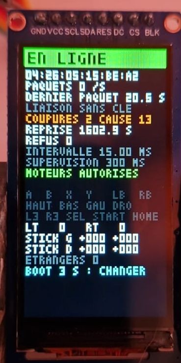
The fraction of a second, however, is configured but not yet proven. The controller accepted a 300 ms supervision timeout instead of the six seconds it proposed, and the board notices at once when the controller ends the link; what remains is to cut it off outright, inside a metal box, to measure how long the robot would really take to stop.
Three ideas carried the journey, and they apply far beyond this controller.
A device’s description is not what it does. The controller described itself as an HID controller, but spoke elsewhere. Displaying raw bytes without assuming anything about their format settled in minutes what hours of reading descriptions would not have settled.
In BLE, the central chooses. Saving an address and calling only that one is enough to shut out other controllers, without any key.
A silent link is not a dead link. Monitoring data meant confusing an idle controller with a lost one. The radio exchanges a packet at every rendezvous, even an empty one: that is where we needed to look, and the central sets how long it tolerates silence.
The question remains that only a real competition hall can answer: is a 300 ms supervision timeout, amid dozens of Wi-Fi and Bluetooth links, short enough for safety and long enough to avoid stopping the robot at every burst of interference?
The complete programs
Each trial has its own program, complete and ready to build. The archives contain only the source code: there is nothing else to download apart from ESP-IDF, and each one builds with the three commands in the “Building and flashing” section. They follow the story: each keeps what its trial had learnt, and the faults it had not yet noticed.
Trial 01, the display: essai-01-ecran-st7789.zip. The program draws the test pattern, then moves a small square back and forth. It needs only the display, wired as in the trial 01 table. The four panel settings, marked “À RÉGLER”, are at the start of main/essai_ecran.cpp.
Trial 02, the controller over Bluetooth: essai-02-manette-ble.zip. This is ESP-IDF’s esp_hid_host example, with its three corrections, marked [essai 02] in the source code; its licence, Unlicense or CC0-1.0, is at the top of each file. It shows nothing on the display: everything is read in the console. Its scan lasts only five seconds, once, at start-up: put the controller in pairing mode (switch on V3, HOME held for three seconds) before starting the board, or press RST just afterwards.
Trial 03, display everything, bit by bit: essai-03-manette-et-ecran.zip. This is the program behind the grid in video 1, with the display driver and the trial 02 scan stored in components/. Its scan restarts on its own as long as no controller is connected. It erases all pairings at every start-up: after an RST, put the controller back in pairing mode. It keeps the banner fault described above.
Trial 04, the hardened link, the final program: manette-ble-esp32-s31.zip. This is the one described in “Reproducing the build” and in most of the code extracts. The archive contains:
CMakeLists.txt,sdkconfig.defaults, andpartitions.csv: the project, its settings, and the flash memory layout.main/essai_liaison.cpp: the program, in nine commented sections (settings, link states, the latest packet, Bluetooth events, settings memory, the “liaison” task, the BOOT button watch, display, and Bluetooth startup).components/ecran_st7789/: the display driver, with its 3 × 5-pixel font.
All settings you might want to change are grouped at the start of main/essai_liaison.cpp, in the “0. Les réglages” section: display pins, BOOT hold duration, connection parameters, the signal threshold for learning a controller, and CHIFFRER.
The source code, its comments, and the display and console messages remain in French, as shown in the examples and photographs.
Sources and lineage
- Espressif, ESP32-S31 Function-CoreBoard-1, User Guide: J2 connector pinout, USB ports, and buttons; and the board schematic, version 1.0 dated May 13, 2026.
- Espressif, ESP-IDF documentation: Bluedroid GATT client and BLE security APIs; the
examples/bluetooth/esp_hid_hostexample, the starting point for trial 02. - Bluetooth SIG, Bluetooth Core Specification, Volume 6, Part B (Link Layer): connection interval, latency, supervision timeout, and the condition relating them.
- Sitronix, ST7789V datasheet: command codes for
CASET(0x2A) andINVOFF(0x20). - G6 controller manual, on manuals.plus, accessed November 20, 2026: recording and clearing macros on M1 and M2, turbo button.
Photographs and video: Sébastien Debucquoi.
The programs in the archives are released under the PolyForm Noncommercial License 1.0.0: you may use, modify and share them for personal, educational, research or charitable purposes; any commercial use requires the author’s written permission. The Espressif files they contain keep their own licence.